Instrumentation Control Loop Diagrams Instrument Loop Diagra
System instrumentation control engineering scada automation pid course process systems mechanical electrical controls bsc engineers architects must graphic read diagrams Loop instrumentation control How-to create instrument loop diagram (ild)
How a Process Control Loop Works in Automatic Control Systems
How-to create instrument loop diagram? Industrial instrumentation and control: basics of a control loop What is an instrumentation loop diagram?
Basics of instrument loop diagrams ~ learning instrumentation and
What is a loop diagram and how to interpret it? instrumentation andInstrument loop diagrams Loop wiring diagram instrumentation pdfInstrumentation loop diagrams.
Loop diagram questions instrumentation control typeLoop instrument instrumentation basics Loop diagram instrument instrumentation drawing diagrams cable ild field transmitter create sample marshalling pressure functional single details mounted cardLoop diagram and system inspection lab exercise.

What instrumentation loop diagram is (loop diagram)?
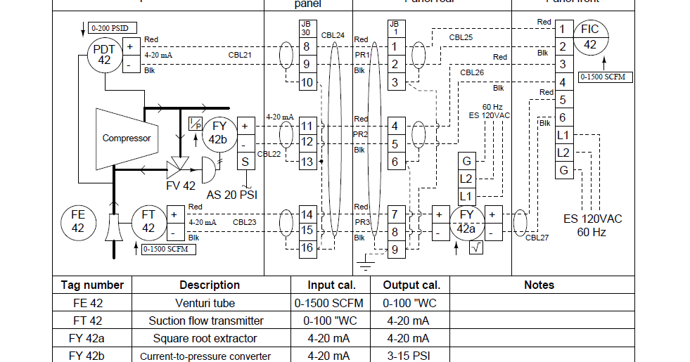
Instrument loop wiring diagramInstrument diagrams marshalling ild junction The loop diagram is divided into sections that organize informationInstrumentation ild diagrams transmitter marshalling signal.
Instrumentation loop diagramsHow-to create instrument loop diagram? Instrument loop diagramsLoop diagrams (loop sheets).

Loop diagram instrument instrumentation basics number
Loop diagram instrument wiring instrumentation pdf drawings diagrams control excel basics engineering engineersCircuit diagram power loop test loop Basics of instrument loop diagrams ~ learning instrumentation andInstrument loop instrumentation drawing diagrams control engineering learning typical.
Instrument loop diagram basicsInstrumentation diagrams instrumentationtools active What is instrument loop diagramWhat is a loop diagram and how to interpret it? instrumentation and.
How a process control loop works in automatic control systems
Instrumentation loop diagramsIndustrial instrumentation and control: loop diagrams Control loop diagram process basics system valve engineering instrumentation industrial basic point consider systems valves variables electrical article following letLoop wiring diagram instrumentation pdf.
Instrument loop instrumentation drawing control diagrams engineering typicalInstrumentation instrumentationtools 15 loop diagram questionsInstrument loop diagrams.

Instrument loop diagram basics
Instrumentation typicalInstrumentation wiring surge automation Basics of instrument loop diagrams ~ learning instrumentation andLoop instrumentation diagrams control diagram instrumentationtools number system wiring process logic junction box instruments surge compressor flow 6d tools piping.
Pid control designInstrumentation design & detail engineering Instrumentation loop diagrams.


What is an Instrumentation Loop Diagram? - Field Instrumentation

Instrument Loop Diagrams
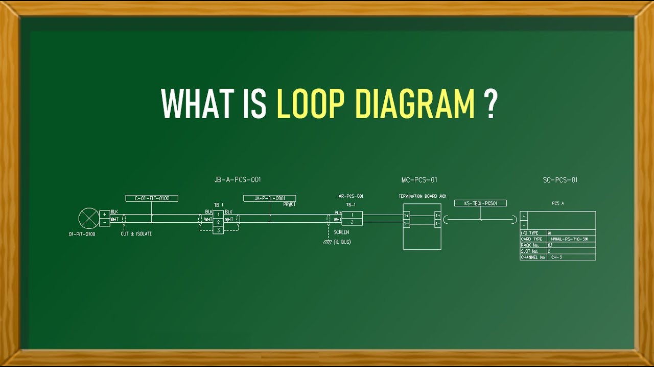
What is Instrument Loop Diagram - YouTube

The loop diagram is divided into sections that organize information

Instrument Loop Diagrams
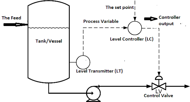
Industrial Instrumentation and Control: Basics of a Control Loop

What Instrumentation Loop Diagram Is (LOOP DIAGRAM)?